
Realisation
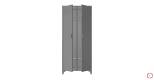
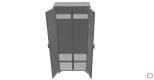
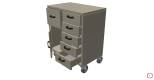
Szafka metalowa 1

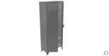

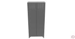


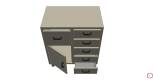
Szafka metalowa 2


If we take a closer look at the solutions currently used in the industrial sector, we will notice a certain trend. Structures made of bent or pressed sheet metal parts are widely used. They are used both for small and large products. One might even be tempted to say that they are used in any production or service facility in any industry. They are used as components in machine and equipment housings, cabinets, switchboxes, workbenches and much more. Designing such parts in current 3D programmes can be compared to origami. Although the work is not necessarily realised from a square sheet of metal.
Engineering practice shows that the more trivial an issue seems, the more mistakes can be made. Serious construction challenges require a lot of time spent on technical and economic analysis, selection of the right material, optimal shape, calculations, and finally checking and approving the documentation. In the case of sheet metal construction, some steps are sometimes skipped or not even taken at all. This is usually due to the huge amount of work that takes place in the construction facilities. Therefore, it is sometimes more efficient to scrap a small device made of just bent sheets than to have it analysed in depth by several engineers.
Despite appearances, with supposedly “simple” sheet metal structures, many tricks and solutions can be used to not only assemble a device or piece of furniture, but to reduce assembly time and eliminate or minimise mistakes on the production side.
The sheet metal construction process
For many years, CAD software for computer aided design has included a tool or module for making sheet metal structures. The most important function is the ability to generate the development of a model. This is then saved in an appropriate format (usually *.dxf) which is loaded on the operator panel of the cutting machine. Moreover, it is placed on the manufacturing drawings with the description of bending lines, angles, radii of punches or dies and appropriate distances.
When designing equipment or furniture, for example a cupboard or a workbench, many sheet metal parts are taken into account. The generated developments are then nestled, i.e. optimally positioned on the sheet to minimise the amount of waste. Separate applications are used for this process. All the nested sheets are stored in a single file. It is then sent to the computer that controls the cutting machine. The operator only has to load the file and insert the correct sheet into the machine (dimensions, material).
Bends are then made on the cut out components using press brakes, on the basis of appropriately prepared manufacturing documentation. Bended components often still need to be welded (e.g. to close or seal corners). They are also subjected to further mechanical treatments such as grinding and honing. The finished parts, as long as they are not subject to technical coating or painting processes, are ready for final assembly into a product.
Techniques for cutting out sheet metal parts
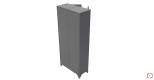
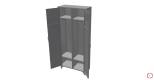
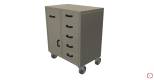
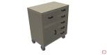
The most frequently used cutting techniques for cutting out sheet metal elements are laser, plasma, water and, less frequently, progressive presses. We have made several sheet metal cabinets for our customer. The effects of our work are presented in the photographs below.
We would be happy to work with contractors of such sheet metal constructions throughout the country on an ongoing basis.
If you want to use a similar service, contact us now.